
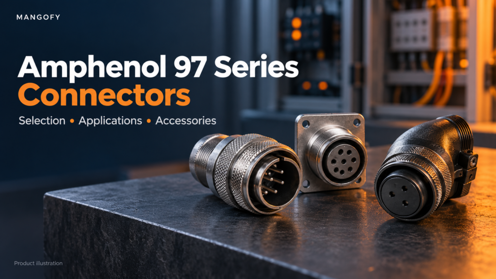
A Amphenol 97 Series connectors connector can look right and still be the wrong part. The shell may fit, but the contact arrangement, insert position, or cable accessory may differ. For a maintenance team, that means another purchase request. For an OEM, it can mean an assembly delay.
Amphenol 97 Series connectors offer a broad choice of configurations for general-duty industrial connections. That flexibility is useful, provided the selection starts with the application rather than a photograph or an incomplete part number.
This guide explains where the series fits, how its main options differ, and what engineers, panel builders, and purchase teams should check before ordering.
What Are Amphenol 97 Series Connectors?
Amphenol 97 Series circular connectors are metal-bodied electrical connectors used for general-duty power and signal connections. Their cylindrical construction, threaded coupling and choice of contact arrangements make them suitable for many commercial and industrial equipment designs.
The catalogue describes six shell styles and 128 contact arrangements covering 1 to 52 circuits. Solder-contact and rear-release crimp-contact versions are available, with separate selection and ordering details.
“Circular” describes the connector’s round interface, while “cylindrical” describes its overall body form. Consequently, searches for Amphenol 97 Series cylindrical connectors generally refer to the same product family rather than a separate range.
The important distinction is between the family name and the complete configuration. A series name alone does not identify the connector you need.
Understanding MIL-5015 Style and SAE AS50151 References
You may see the 97 Series described as an Amphenol 97 Series MIL-5015-style connector. Amphenol’s catalogue also references SAE AS50151, reflecting the connector architecture associated with this family.
For buyers searching for Amphenol MIL-5015 style connectors, the word “style” matters. It should not be treated as confirmation that every commercial part meets a project’s military qualification or environmental requirements.
Likewise, searches for Amphenol SAE AS50151 connectors can bring up several families with different construction and protection options. The standard 97 Series is presented as a general-duty, non-environmental range.
If a drawing specifies an Amphenol SAE AS50151 cylindrical connector, check the exact series, class, part number, and required documentation. Matching the broad description is only the starting point.
Where Are These Connectors Used?
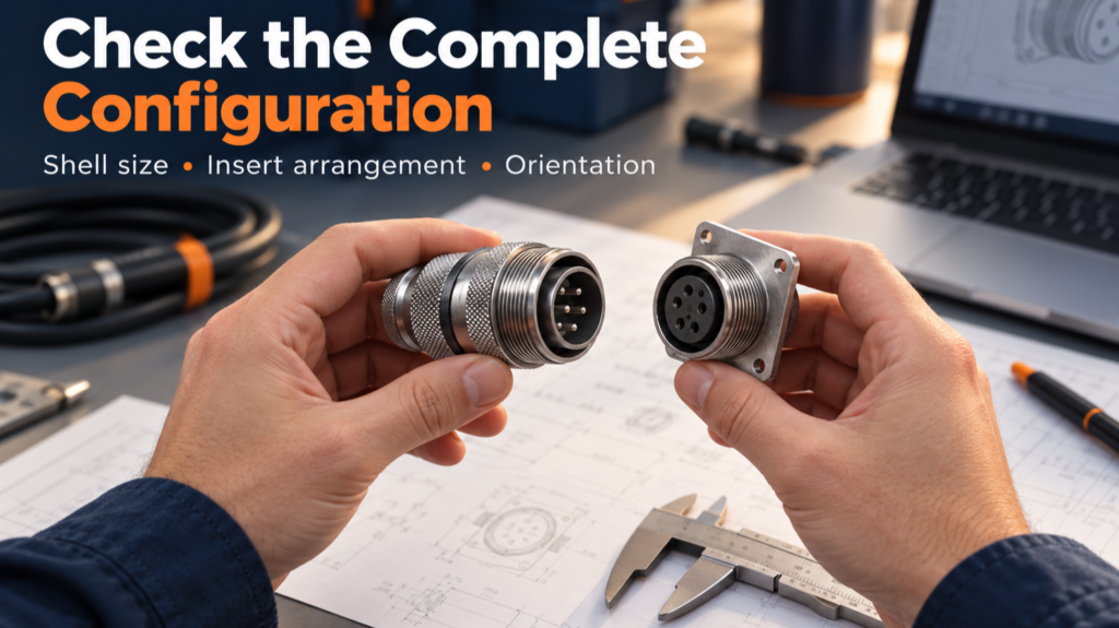
Amphenol identifies automotive equipment, robotics, machine tools, and welding equipment among the applications for the 97 Series. The range also appears in other commercial equipment and instrumentation applications.
For an OEM, the selection question might be whether a connection can carry the required circuits within the available mounting space. For a panel builder, cable routing and access to the coupling may be equally important.
Maintenance teams face a different challenge: identifying a replacement that matches the installed mating half. They need more than the number of pins.
Amphenol 97 Series industrial connectors are worth considering where their electrical, mechanical, and environmental characteristics match the equipment. An application label such as “robotics” does not mean that every variant suits continuous cable movement, washdown, or outdoor exposure.
Choosing the Right Amphenol 97 Series Connectors
The shell determines how the connector mounts and where the cable exits. In the solder-contact range, the catalogue identifies these styles:
| Shell code | Style | Selection consideration |
| 3100 | Wall receptacle | Wall mounting with an extended rear section |
| 3101 | Cable receptacle | Connections involving a cable-mounted receptacle |
| 3102 | Box receptacle | Panel or box mounting with a shorter rear section |
| 3106 | Straight plug | Cable routing directly behind the plug |
| 3107 | Quick-disconnect plug | Applications calling for this specific plug construction |
| 3108 | Angle plug | Cable routing at a right angle |
| – | – | – |
These codes belong to the solder-contact ordering system. Rear-release crimp versions use their own ordering details.
Check the space behind the panel as well as the mounting face. A connector might fit the cutout but leave insufficient room for the cable bend, clamp, or assembly tools.
Also, plug and receptacle describe the shell roles. Either can contain pin or socket contacts; do not assume that “plug” always means pins.
Solder or Crimp: Which Version Should You Choose?
Solder-contact versions use solder cups for wire termination. They may suit a build or repair process already organized around soldering, provided the assembly follows the relevant instructions.
Rear-release crimp versions use contacts terminated with suitable crimp tooling. They offer a different assembly and servicing approach, including contact removal using the appropriate procedure and tools.
The decision should consider:
- Wire size and compatible contact options.
- Available assembly equipment.
- Production volume and inspection methods.
- Maintenance requirements.
- Compatibility with the existing connector arrangement.
For replacement work, identify the installed termination type first. Changing from solder to crimp can affect contacts, tooling, and the assembly process.
Neither method compensates for an incorrectly sized contact or inadequate cable support. Treat termination and strain relief as connected parts of the design.
How to Select an Amphenol 97 Series Connectors
Start with the circuit requirements.
List the number of circuits, current carried by each circuit, operating voltage, and wire sizes. Keep signal and power requirements clear, especially when an insert contains different contact sizes.
Avoid applying a headline family rating to every connector. The selected contacts and insert arrangement must support the actual requirements.
Match the insert arrangement.
Contact count alone is insufficient. Two connectors with similar dimensions may have different layouts or contact sizes.
Use the manufacturer’s arrangement drawing to check contact positions and identification. When replacing a part, compare the arrangement with the existing mating half and the equipment documentation.
Check pin, socket, and insert orientation.
The catalogue uses P for pin contacts and S for socket contacts. It also provides alternate insert positions for applicable arrangements.
These positions help distinguish otherwise similar connections. Where a panel has multiple connectors serving different functions, correct orientation is particularly important.
Review the complete installation.
Confirm mounting dimensions, cable exit direction, cable diameter, accessories, and access for assembly. Review the operating environment before finalizing the part.
A useful purchasing handover includes the complete connector number, mating-part number, and accessory list. This gives procurement a defined assembly to source rather than a description that needs interpretation.
Are Amphenol 97 Series Connectors Waterproof?
The standard 97 Series is described as general-duty and non-environmental. A metal shell should not be taken as proof of waterproof construction.
Amphenol’s product information identifies a splash-proof option involving the 417 suffix and a 97-67 cable clamp. That is a configuration-specific statement, not a protection claim for every 97 Series connector.
For an exposed installation, establish what the connector will encounter: occasional splashes, airborne dust, condensation, cleaning jets, or immersion. These are different conditions.
Then check the documented performance of the complete assembly, including the mating condition and cable entry. If the application needs protection beyond the selected configuration, evaluate a connector designed for that environment.
Gray ZnNi Plating: What Changes?
Shell finish deserves attention when corrosion resistance or material compliance forms part of the specification.
Amphenol’s Gray Zinc/Nickel document describes a cadmium-free plating option with a 500-hour salt-spray rating. It also discusses compatibility with commonly used connector finishes.
For the 97 Series, the document distinguishes two ordering suffixes:
| Suffix | Description in the Gray ZnNi document |
| (959) | No pre-filled solder cups |
| (958) | Solder-filled solder cups; non-RoHS assembly |
This distinction shows why checking the shell finish alone is insufficient when confirming RoHS requirements. The supplied connector assembly matters.
The salt-spray figure describes performance under the specified test conditions. It is not a prediction of service life at a particular installation.
Similarly, corrosion-resistant plating does not create a sealed cable entry or waterproof mating interface. Finish selection and environmental sealing must be checked separately.
Reading the Part Number Before Ordering
A complete part number communicates details that a product photograph cannot.
For example, the catalogue uses 97-3101A-28-21SY(959) to illustrate the solder-contact ordering structure. Its elements identify the series, shell type, shell construction, shell size, insert configuration, socket contacts, alternate insert position, and finish option.
This is an example of how to read an ordering code, rather than a recommendation for a particular application.
When requesting an alternative, retain every suffix and orientation character. A shortened number can remove the very detail that distinguishes the required part.
If the existing marking is difficult to read, provide clear photographs of the marking and mating face, together with the equipment drawing. Ask for confirmation before accepting a proposed substitute.
Accessories and Product Enquiries Through Mangofy
A connector purchase may also require cable clamps, bushings, protection caps or adapters. The 97 Series catalogue covers several accessory types, each serving a different purpose.
For instance, a clamp supports the cable, while the correct bushing helps accommodate it within the intended clamping arrangement. Accessory selection therefore needs to account for dimensions and cable construction.
The following Mangofy product pages provide starting points for enquiries about the specific part numbers:
| Part number | Mangofy product page |
| 10-070500-012 | View 10-070500-012 |
| 7-8905 | View 7-8905 |
| 97-79-513-28 | View 97-79-513-28 |
| MS3420-28A | View MS3420-28A |
These are separate part-number references, not a confirmed compatible kit. Request the relevant drawing and verify each item against your assembly.
For a quotation, include quantity, delivery requirement, complete part numbers, and any required compliance documentation. Confirm the current specification and supply details before ordering.
Common Questions About Amphenol 97 Series Connectors
Can I select a connector using only its pin count?
No. You also need the shell size, insert arrangement, contact type, orientation, and electrical requirements. A matching pin count does not establish mating compatibility.
Are all 97 Series connectors RoHS compliant?
Do not assume so. Compliance depends on the supplied configuration. The Gray ZnNi document specifically distinguishes the (959) and (958) options, including their solder-cup differences.
Can a 97 Series connector mate with an SAE AS50151 connector?
Amphenol describes intermateability for applicable configurations. Confirm the exact shell size, arrangement, contacts, and orientation of both parts rather than assuming every connector in either family will mate.
Does a corrosion-resistant finish make it suitable for outdoor use?
Not by itself. Outdoor suitability depends on the complete assembly and expected exposure, including sealing, cable entry, and operating conditions.
